This watch has already been reviewed several times, but I hope that my review will also be interesting to you. Added job description and instructions.
The designer was bought on ebay.com for 1.38 pounds (0.99+0.39 shipping), which is equivalent to $2.16. At the time of purchase, this is the lowest price offered.
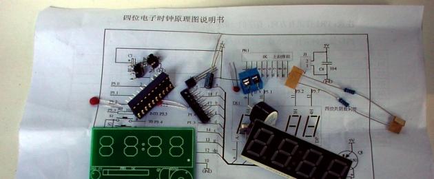
Delivery took about 3 weeks, the set came in a regular plastic bag, which in turn was packed in a small bubble bag. There was a small piece of foam on the indicator terminals; the rest of the parts were without any protection.
From the documentation there is only a small A5 sheet of paper with a list of radio components on one side and a circuit diagram on the other. 
1. Electrical circuit diagram, parts used and operating principle

The basis or “heart” of the watch is an 8-bit CMOS microcontroller AT89C2051-24PU equipped with a 2kb Flash programmable and erasable ROM.
Clock generator node assembled according to the circuit (Fig. 1) and consists of a quartz resonator Y1, two capacitors C2 and C3, which together form a parallel oscillatory circuit.

By changing the capacitance of the capacitors, you can change within small limits the frequency of the clock generator and, accordingly, the accuracy of the clock. Figure 2 shows a variant of a clock generator circuit with the ability to adjust the clock error.
Initial reset node serves to set the internal registers of the microcontroller to the initial state. It serves to supply, after connecting power, to 1 pin of the MK a single pulse with a duration of at least 1 μs (12 clock periods).
Consists of an RC circuit formed by resistor R1 and capacitor C1.
Input circuit consists of buttons S1 and S2. The software is designed so that when you press any of the buttons once, a single signal is heard in the speaker, and when you hold it, a double signal is heard.
Display module assembled on a four-digit seven-segment indicator with a common cathode DS1 and a resistive assembly PR1.
A resistive assembly is a set of resistors in one housing: 
Sound part The circuit is a circuit assembled using a 10 kOhm resistor R2, a pnp transistor Q1 SS8550 (acting as an amplifier) and a piezoelectric element LS1.
Nutrition supplied through connector J1 with smoothing capacitor C4 connected in parallel. Supply voltage range from 3 to 6V.
2. Assembling the constructor
The assembly did not cause any difficulties; it was written on the board where to solder what parts.Lots of pictures - the assembly of the construction set is hidden under the spoiler
I started with the socket, since it is the only one that is not a radio component: 
The next step was to solder the resistors. It is impossible to confuse them, they are both 10 kOhm: 
After that, I installed on the board, observing the polarity, an electrolytic capacitor, a resistor assembly (also paying attention to the first pin) and elements of a clock generator - 2 capacitors and a quartz resonator 
The next step is to solder the buttons and the power filter capacitor: 
After this, it’s time for the sound piezoelectric element and transistor. The main thing in a transistor is to install it on the correct side and not to confuse the terminals: 
Lastly, I solder the indicator and power connector: 
I connect it to a 5V source. Everything is working!!! 
3. Setting the current time, alarms and hourly signal.
After turning on the power, the display is in the mode ("HOURS: MINUTES") and displays the default time of 12:59. The hourly beep is on. Both alarms are on. The first is set to operate at 13:01, and the second at 13:02.
Each time you briefly press the S2 button, the display will switch between the modes (“HOURS: MINUTES”) and (“MINUTES: SECONDS”).
When you press the S1 button for a long time, you enter the settings menu, which consists of 9 submenus, designated by the letters A, B, C, D, E, F, G, H, I. Submenus are switched by the S1 button, the values are changed by the S2 button. Submenu I is followed by exiting the settings menu.
A: Setting the current time clock
When you press the S2 button, the clock value changes from 0 to 23. After setting the clock, you must press S1 to go to submenu B. 
B: Setting the minutes of the current time
C: Turn on the hourly beep
The default is ON – a beep sounds every hour from 8:00 to 20:00. Pressing the S2 button changes the value between ON and OFF. After setting the value, you must press S1 to go to submenu D. 
D: Turn on/off the first alarm
By default, the alarm is ON. Pressing the S2 button changes the value between ON and OFF. After setting the value, you must press S1 to go to the next submenu. If the alarm is turned off, submenus E and F are skipped. 
E: Setting the first alarm clock
When you press the S2 button, the clock value changes from 0 to 23. After setting the clock, you must press S1 to go to submenu F. 
F: Setting the minutes of the first alarm
When you press the S2 button, the minutes value changes from 0 to 59. After setting the minutes, you must press S1 to go to submenu C. 
G: Turn on/off the second alarm clock
By default, the alarm is ON. Pressing the S2 button changes the value between ON and OFF. After setting the value, you must press S1 to go to the next submenu. If the alarm is turned off, submenus H and I are skipped and the settings menu is exited. 
H: Setting the second alarm clock
When you press the S2 button, the clock value changes from 0 to 23. After setting the clock, you must press S1 to go to submenu I. 
I: Setting the minutes of the second alarm
When you press the S2 button, the minutes value changes from 0 to 59. After setting the minutes, you must press S1 to exit the settings menu. 
Seconds correction
In the mode (“MINUTES: SECONDS”), you must hold down the S2 button to reset the seconds. Next, briefly press button S2 to start counting the seconds. 
4. General impressions of the watch.
Pros:+ Low price
+ Easy assembly, minimum parts
+ The pleasure of self-assembly
+ Fairly low error (I was a few seconds behind during the day)
Minuses:
- Doesn't keep time after power off
- Lack of any documentation other than the diagram (this article partially solved this disadvantage)
- The firmware in the microcontroller is protected from reading
5.Additionally:
1) On the endless expanses of the Internet, I found instructions for this watch in English and translated it into Russian. You can download it3.1.1. Electrical circuit of an electronic clock on an LCD
The liquid crystal indicator consists of two flat glass plates glued around the perimeter so that there is a gap between the glasses; it is filled with special liquid crystals.
On both plates, the indicator segments themselves are drawn with a special substance that is transparent and conducts electric current. Usually one of the plates acts as a common wire.
Liquid crystal indicators work with polarized light - for this purpose, special film polarizers are glued to both sides of the indicator. Depending on the relative position of the polarizers, the LCD may be positive(dark symbols on a light background - as in watches, microcalculators) and negative(transparent symbols on a black background - used in car radios). Liquid crystals, in the absence of current flowing through them, are located inside the indicator in a chaotic manner and practically do not block the light, i.e. all segments are transparent. When a potential difference occurs between some segments on both sides of the glass, the liquid crystals in this place are orderedly arranged across the light flux, blocking it, and the corresponding segment becomes opaque. Moreover, by changing the magnitude of the applied voltage, you can change the degree of opacity of the indicator.
Liquid crystals- dielectric, i.e. they do not conduct electric current. Therefore, they can only be controlled by alternating voltage: after all, two plates of LCD glass are practically a capacitor, and when an alternating voltage is applied to the terminals of the capacitor, current flows through it. Liquid crystals require negligible current, so the frequency of the control voltage can be quite low (50...100 Hz). At the top of the range, this frequency is practically unlimited, but it is not recommended to make it higher than 1 kHz - the conductors with which the segments are drawn have a finite resistance (usually 1...10 kOhm), so as the frequency increases, the contrast of the indicator will deteriorate. At the same time, thanks to this resistance, the indicator is insensitive to voltage overloads - it can withstand voltages up to 30...50 V (in this case, the segments, sometimes together with the tracks, turn black, and after removing the voltage become transparent for several minutes, while all the others indicators fail even with double overloads. But still, despite the absence of visible damage, you should not get too carried away with overloading the LCD - this sharply reduces its service life, in particular, reduces the contrast.
To control the LCD, “Exclusive OR” logic elements are usually used; one of the inputs of all elements is connected together and connected to the generator and the common output of the LCD, and control signals are supplied to the second input of the element. As is known, these elements, at a “logical zero” level at one of the inputs, work as repeaters of the level from the other input (that is, the voltage difference between the output of the element and the general indicator is zero - the segment is not visible), and at “one” - as inverters, and the corresponding indicator segment becomes visible. Thus, in order to “illuminate” a segment, a “one” must be supplied to the input of the element.
In addition, to work with the LCD it is convenient to use microcircuits of the K176 series: K176IE3 (counter-divider by 2 and 6), K176IE4 (counter-divider by 4 and 10) and K176ID2 or K176ID3 (binary decimal decoders, only K176ID3 has more powerful outputs ). All of these microcircuits already have “Exclusive OR” elements at their outputs, which greatly simplifies the device circuit.
In Fig. Figure 3.1 shows a diagram of a simple electronic clock consisting of a minimum of parts. For greater convenience, a zero extinguishing unit in the tens of hours category has been added to the circuit.
A quartz oscillator is assembled on a specialized K176IE12 microcircuit; any “clock” quartz can be used as a ZQ1 quartz resonator. The generator frequency can be adjusted by changing the capacitance of capacitor C1. At pin 4 of the microcircuit, second pulses are formed - they are used to blink the dividing point, at pin 10 second pulses are already divided by 60. Thus, minute pulses are obtained. They go to the line of counters DD2...DD5: DD2 counts units of minutes, DD3 - tens of minutes, etc. A clock reset circuit is assembled on diode VD2 and resistor R8 - as soon as the clock counts to 24, levels will appear at outputs 4 DD4 and 2 DD5 logical “1”, which will reset all counters. While the number of clocks is less than 24, at least one of these pins has a logical level “0”, which prohibits reset.
Since the DD1 chip does not have a relatively low-frequency output, we had to use clock outputs T1...T4. A simple adder is assembled on elements R3 and VD1, thanks to which at the point of connection of these elements there is a correct square wave with a frequency of 256 Hz. It is used to operate the LCD.
The decimal point control circuit is assembled on elements DD6.1, DD6.2 (all other points and additional segments must be connected to the common wire of the indicator). Element DD6.2 performs the function of an inverter (at logical level “1” at the control input, it is closed and supplies level “0” to DD6.1, at “0” it is open and “1” is sent to input DD6.1 through resistor R4) , element DD6.1, depending on the level at the “1 Hz” output, supplies either a direct or an inverted generator signal to the “dot” segment, i.e. the dot will be visible for 0.5 seconds, and the next 0.5 sec - no.
Of course, it would be easier to assemble this node on one “Exclusive OR” element, but it would be impossible to assemble a circuit for extinguishing the extra zero using the remaining elements, and introducing an extra microcircuit into the circuit is logically unreasonable.
This very zero cancellation unit is assembled on elements DD6.3 and DD6.4. It is easy to notice that in the most significant digit, the f segment will be visible only with the digit code 0; with the digit codes 1 and 2, this segment is not illuminated. Therefore, it would be quite logical to use this decoder output for our analyzer. When the logical level is “1” at the output of the generator, element DD6.4 is connected to the output f of the decoder, and charges or discharges capacitor C3. At this time, at pin 6 of the DD5 microcircuit, the logical level is “1”. Thus, when the digit code is “0”, the output of segment f will be a logical level “0”, and when the digit codes are 1 or 2 there will be a logical level “1”. The corresponding level is on capacitor C3. At the logical level “1” on this capacitor, element DD6.3 is closed, and the DD5 microcircuit operates in the same way as other counters - the tens of hours digit is visible, at the logical level “0” on capacitor C3, element DD6.3 is open, and the counter outputs don't switch.
This text is an introductory fragment. From the book Amazing Mechanics author Gulia Nurbey VladimirovichElectric “capsule” The author is once again convinced of the omnipotence of electricity, as well as the fact that he is still very far from realizing his dream... How to accumulate electrons? Yes, if thermal storage devices didn’t lead me into the wilds, they certainly sent me down the wrong path.
From the book Rules for Electrical Installations in Questions and Answers [A manual for studying and preparing for a knowledge test] author Krasnik Valentin ViktorovichElectrical part Question. In accordance with what requirements is the selection of battery equipment made?Answer. Selection of electric heating devices, lamps, ventilation motors and electrical wiring for main and auxiliary
From the book Instrumentation author Babaev M A35. Elements of electronic circuits of IP Why are electronic devices needed in IP (measuring instruments)? For a variety of purposes: from amplifying weak sensor signals to converting or generating signals of various shapes and frequencies. In their manufacture, they are used
From the book Inventions of Daedalus by Jones DavidElectrical cleaning From the point of view of chemical technology, washing dishes is an extremely uneconomical process: in order to wash off a little dirt, a huge amount of water is consumed. Even more blatant examples of wastefulness are given to us by washing and bathing, and many
From the book Creating an Android Robot with Your Own Hands by Lovin JohnElectrical part In Fig. Figure 11.17 shows a diagram for controlling servomotors using a PIC microcontroller. The servomotors and microcontroller are powered by a 6 V battery. The 6 V battery compartment contains 4 AA cells. The microcontroller circuit is assembled on a small
From the book Show/Observer MAKS 2011 author author unknownElectrical circuit The electrical circuit is an electronic switch controlled by the intensity of the light flux. When the level of average ambient illumination is low (the threshold value can be adjusted), the circuit turns off the power to the gear motor.
From the book Electronic homemade products author Kashkarov A.P.“Frigate Ecojet”: a new aircraft design and a new business plan The MAKS Aviation Show traditionally serves as a showcase for new ideas in aircraft construction. FIG "Rosaviakonsortium" on its own initiative is developing a program to create a wide-body
From the book Electronic Tricks for Curious Children author Kashkarov Andrey Petrovich4.4.2. Timer electrical circuit When the EMT is connected to a 220 V network, voltage is supplied to coil K1 (having a resistance of 3.9 kOhm) through limiting resistor R1. Using a system of gears and voltage applied to this coil (using electromagnetic induction)
From the book Welding author Bannikov Evgeniy Anatolievich4.8. How to localize interference in electronic devices In almost any measurement area, the value of the extremely audible weak signal is determined by noise - an interfering signal that clogs the useful signal. Even if the measured quantity is not small, noise reduces the accuracy
From the book History of Electrical Engineering author Team of authorsAppendix 10 Manufacturers of electronic components and their addresses on the Internet Components for the radio-electronic industry are produced by various manufacturing companies, whose branches are located throughout the world. To avoid confusion with the markings
From the book How to Become a Genius [Life Strategy of a Creative Personality] author Altshuller Genrikh SaulovichChapter 2 Various schemes for modifying electronic toys 2.1. Finalization of “Pig in a Poke” A toy has appeared on sale, which, in accordance with its appearance, is called “Pig in a Poke”. Even with a slight acoustic impact (noise, loud voice, and even more so
From the author's bookChapter 3 Safe remanufacturing of industrial electronics
From the author's book From the author's book7.2. ELECTRIC WELDING 7.2.1. ELECTRIC ARC WELDING Electric arc welding was invented in Russia. N.N. Benardos, on July 6, 1885, applied for and received Department of Trade and Manufactures Privilege No. 11982 (1886) for a method of “joining and separating metals
From the author's book11.3.1. SOURCES OF ELECTRON AND ION FLOWS Electron-ion technology in a broad sense is understood as a set of methods for processing materials and objects with flows of electrons, ions, plasma and neutral atoms. These processes are widely used in metallurgy,
From the author's book15 hours of reward So, to be a creative person, it is not enough to have only a socially useful, significant worthy goal. After all, the set goal must be realized, and desire alone is not enough for this. To cross the ocean, you need to know how to build ships. To
This clock is assembled on a well-known chipset - K176IE18 (binary counter for a clock with a bell signal generator),
K176IE13 (counter for clocks with alarm clock) and K176ID2 (binary to seven-segment code converter)
 When the power is turned on, zeros are automatically written to the hour and minute counter and the alarm clock memory register of the U2 chip. For installation
time, press the S4 (Time Set) button and holding it press the S3 (Hour) button - to set the hour or S2 (Min) - to set
minutes. In this case, the readings of the corresponding indicators will begin to change with a frequency of 2 Hz from 00 to 59 and then again 00. At the moment of transition
from 59 to 00 the hour counter will increase by one. Setting the alarm time is the same, you just need to hold it
button S5 (Alarm Set). After setting the alarm time, you need to press the S1 button to turn on the alarm (contacts
closed). Button S6 (Reset) is used to force the minute indicators to be reset to 00 during setup. LEDs D3 and D4 play a role
dividing dots flashing at a frequency of 1 Hz. The digital indicators on the diagram are located in the correct order, i.e. come first
hour indicators, two dividing dots (LEDs D3 and D4) and minute indicators.
The clock used resistors R6-R12 and R14-R16 with a wattage of 0.25W, the rest - 0.125W. Quartz resonator XTAL1 at a frequency of 32 768Hz -
ordinary sentry, KT315A transistors can be replaced with any low-power silicon of the appropriate structure, KT815A - with transistors
average power with a static base current transfer coefficient of at least 40, diodes - any low-power silicon. Tweeter BZ1
dynamic, without built-in generator, winding resistance 45 Ohm. Button S1 is naturally locked.
 The indicators used are TOS-5163AG green, you can use any other indicators with a common cathode without reducing
resistance of resistors R6-R12. In the figure you can see the pinout of this indicator; the conclusions are shown conditionally, because presented
view from above.
After assembling the watch, you may need to adjust the frequency of the crystal oscillator. This can most accurately be done by digitally controlling
using a frequency meter, the oscillation period is 1 s at pin 4 of the U1 microcircuit. Tuning the generator as the clock progresses will require significantly more expense
time. You may also have to adjust the brightness of LEDs D3 and D4 by selecting the resistance of resistor R5, so that everything
glowed uniformly brightly. The current consumed by the clock does not exceed 180 mA.
The watch is powered by a conventional power supply, assembled on a positive microcircuit stabilizer 7809 with an output voltage of +9V and a current of 1.5A.
I present to your attention electronic microcontroller clock. The clock circuit is very simple, contains a minimum of parts, and can be repeated by beginning radio amateurs.
The design is assembled on a microcontroller and a DS1307 real-time clock. A four-digit, seven-segment LED indicator is used as an indicator of the current time (ultra-bright, blue-colored, which looks good in the dark, and, at the same time, the clock plays the role of a night light). The clock is controlled by two buttons. Thanks to the use of the DS1307 real-time clock chip, the program algorithm turned out to be quite simple. The microcontroller communicates with the real-time clock via the I2C bus, and is organized by software.
Clock diagram:
Unfortunately, there is an error in the diagram:
— the MK terminals need to be connected to the transistor bases:
РВ0 to Т4, РВ1 to Т3, РВ2 to Т2, РВ3 to Т1
or change the connection of the transistor collectors to the indicator digits:
T1 to DP1…..T4 to DP4

Parts used in the clock circuit:
♦ ATTiny26 microcontroller:

♦ real time clock DS1307:

♦ 4-digit seven-segment LED indicator – FYQ-5641UB-21 with a common cathode (ultra-bright, blue):

♦ quartz 32.768 kHz, with an input capacitance of 12.5 pF (can be taken from the computer motherboard), the accuracy of the clock depends on this quartz:

♦ all transistors are NPN structures, you can use any (KT3102, KT315 and their foreign analogues), I used BC547S
♦ microcircuit voltage stabilizer type 7805
♦ all resistors with a power of 0.125 watts
♦ polar capacitors for an operating voltage not lower than the supply voltage
♦ backup power supply DS1307 – 3 volt lithium cell CR2032
To power the watch, you can use any unnecessary cell phone charger (in this case, if the voltage at the output of the charger is within 5 volts ± 0.5 volts, part of the circuit - a voltage stabilizer on a 7805 type chip - can be eliminated)
The current consumption of the device is 30 mA.
You don’t have to install the backup battery for the DS1307 clock, but then, if the mains power goes out, the current time will have to be set again.
The printed circuit board of the device is not given; the design was assembled in a case from a faulty mechanical watch. The LED (with a blinking frequency of 1 Hz, from the SQW DS1307 pin) serves to separate the hours and minutes on the indicator.
The microcontroller settings are factory: clock frequency - 1 MHz, FUSE bits do not need to be touched.
Clock operation algorithm(in Algorithm Builder):

1. Setting the stack pointer
2. Setting timer T0:
— frequency SK/8
- overflow interrupts (at this preset frequency, the interrupt is called every 2 milliseconds)
3. Initialization of ports (pins PA0-6 and PB0-3 are configured as output, PA7 and PB6 as input)
4. Initialization of the I2C bus (pins PB4 and PB5)
5. Checking the 7th bit (CH) of the DS1307 register zero
6. Global interrupt enable
7. Entering a loop and checking if a button is pressed
When turned on for the first time, or turned on again if there is no backup power to the DS307, the current time is reset to the original setting. In this case: button S1 – to set the time, button S2 – transition to the next digit. Set time - hours and minutes are written to the DS1307 (seconds are set to zero), and the SQW/OUT pin (7th pin) is configured to generate square wave pulses with a frequency of 1 Hz.
When you press the S2 button (S4 - in the program), a global interruption is disabled, the program goes into the time correction subroutine. In this case, using the S1 and S2 buttons, tens and units of minutes are set, then, from 0 seconds, pressing the S2 button records the updated time in the DS1307, resolves the global interrupt and returns to the main program.
The watch showed good accuracy, the time loss per month was 3 seconds.
To improve accuracy, it is recommended to connect quartz to the DS1307, as indicated in the datasheet:

The program is written in the Algorithm Builder environment.
Using the clock program as an example, you can familiarize yourself with the algorithm for communicating between the microcontroller and other devices via the I2C bus (each line is commented in detail in the algorithm).

Photo of the assembled device and printed circuit board in .lay format from site reader Anatoly Pilguk, for which many thanks to him!


The device uses: Transistors - SMD BC847 and CHIP resistors
Attachments to the article:
(42.9 KiB, 3,304 hits)
(6.3 KiB, 4,247 hits)
(3.1 KiB, 2,707 hits)
(312.1 KiB, 6,002 hits)
The second version of the clock program in AB (for those who cannot download the upper one)
(11.4 KiB, 1,999 hits)
The choice of the series of microcircuits on which this circuit will be implemented is extremely important. For a clock, the most important parameter is the current consumed by it, since in most cases either the entire clock or part of the clock circuit is powered by batteries. Therefore, when developing a circuit, we will choose microcircuits implemented in .
Let's start developing the clock circuit with a quartz oscillator. As already discussed when developing the block diagram, a clock quartz resonator will be used as part of the generator. To reduce the cost of the entire device as a whole, we will use the simplest generator circuit - a capacitive three-point, and since the generator is designed to synchronize a digital device, the generator will be implemented on a logical inverter. The schematic diagram of such a quartz oscillator is shown in Figure 1.
Figure 1. Crystal oscillator circuit based on a logic inverter
Let me remind you that resistor R1 is designed to automatically start the generator when the power is turned on. The same element determines the gain of the inverter, and the greater this gain is, the more rectangular oscillations will be formed at its output, and this, in turn, will lead to a decrease in the current consumed by the quartz oscillator. Let's choose R1 equal to 10 Mohm.
R2 is designed to prevent self-excitation of the generator at a frequency determined by the capacitance of the crystal holder. Let's choose the resistance value of this resistor 510 kOhm.
The second one in the generator circuit is designed to reduce the duration of the fronts of the generated rectangular oscillation. This is necessary to reduce the influence of the subsequent circuit on the stability of the master oscillator oscillations, as well as for more reliable operation of the frequency divider digital counters.
As a microcircuit containing inverters, we will choose the SN74LVC2G04DRL microcircuit. This chip, built using CMOS technology, contains two inverters. The fact that the microcircuit contains two elements is indicated by the designation 2G. The fact that these are inverters is indicated by the number 04, and the fact that the microcircuit uses a package with a lead pitch of 0.5 mm is indicated by the letters DRL. The dimensions of the case of this microcircuit do not exceed 1.6 * 1.6 mm (the case has only six pins). The microcircuit is capable of operating in a voltage range from 1.5 to 5.5 V.
Next we implement a frequency divider circuit up to a value of 1 Hz. Let me remind you that the period of oscillations with a frequency of 1 Hz is equal to 1 second. As we already determined when developing the block diagram, its division coefficient should be equal to 32768. That is, to implement the divider, 15 counting triggers will be required. Of course, you can take the K176IE12 chip, specially designed for this purpose, but we are not looking for easy ways, so we use the universal SN74HC393PW chip. It has two independent four-bit binary counters. This means that only two microcircuits will be enough to implement our divider.
The case dimensions of the selected microcircuit do not exceed 5´6.4mm. The body of this microcircuit has 14 pins. If there are no special requirements for the dimensions of the watch, then you can use the domestic K1564IE19 microcircuit. Its case is more than twice larger than the case of the selected microcircuit. However, even the pin numbers of the microcircuits will be the same. The resulting circuit diagram of the second pulse generator of an electronic clock is shown in Figure 2.

Figure 2. Divider circuit for 32768 second pulse generator
Now remember that the time interval generator requires another frequency divider. The pulse period at its output will be equal to 1 minute. The divider by sixty can be implemented on exactly the same chip that we used earlier to build a divider by 32768.
The divisor by sixty is not a multiple of a power of two, so implementing it will require feedback. To simplify the diagram, note that the number 60 is divided into the numbers 10 and 6. Both numbers contain only two ones. The pins of the 4-bit counters go to different sides of the microcircuit body. Therefore, it will be convenient to use two independent logical elements “2I”. This will significantly simplify the layout of the printed circuit board and reduce the length of the connecting wires, thereby reducing the area of the printed circuit board and possible interference from the operating circuit.
We use two SN74LVC1G08DRLR microcircuits as “2I” logic elements. We determine that the microcircuit contains only one logical element by the symbols 1G, and that it is a logical element “2I” by the numbers 08. The dimensions of the case of the selected microcircuit do not exceed 1.6 × 1.6 mm. Domestic versions of such a microcircuit, for example K1554LI1, contain four logic elements in one package, the distance between the pins is at least 1.25 mm. As a result, a circuit assembled on such microcircuits will be identical in electrical parameters, but will be smaller in size.
The resulting frequency divider circuit by 60, generating pulses with a period of 1 minute and consisting of serially connected dividers by 10 and by 6, is shown in Figure 3. The circuit is implemented on only three microcircuits. Using feedback from pins Q1 and Q3 turns binary counter D1.1 into decimal, and using feedback from pins Q1 and Q2 of chip D1.2 implements a modulo 6 counter.

Figure 3. Divider circuit for 60 minute pulse generator
So, we have completed the development of a minute pulse generator. In total, we needed six chips, three of which are small logic chips and take up minimal space on the printed circuit board of a digital device.
Now we can begin to develop the circuit diagram of the time interval counter. As we already found out when developing the block diagram of the clock, this counter includes exactly the same divider by 60 as in the minute pulse generator, so you can use the same circuit. The only difference is that this time we will need all the counter outputs. We will suppress the signals from these pins to the input of the display unit.
The last counter that we need to implement the time interval counter block is a counter for 24. It would be convenient to implement this counter on a decimal counter chip, but dual asynchronous decimal counter chips are not produced, so we implement the clock counter on the same chip as the others clock blocks - SN74HC393PW.
The difficulty in implementing this scheme is that the counting coefficient is not a multiple of ten, so the feedback signal must be applied to both counters simultaneously. It would be possible to implement this counter in binary form, but then there would be difficulties with displaying the contents of this counter. In order to implement a decimal counter on the first 4-bit counter and at the same time be able to reset the entire hour counter at the beginning of the day, we use an additional logical element “2OR”. A reset signal at the output of this microcircuit will appear either when the first counter reaches the number 10, or when the entire counter reaches the value 24.
As a logical element “2OR” we use a small logic microcircuit, similar to the already used “2I” microcircuit. This is the SN74LVC1G32DRLR chip. The number 32 in the name of the microcircuit designates the logical element “2OR”. The case dimensions of this microcircuit do not exceed 1.6´1.6mm. As a result, despite the slightly more complex circuit diagram, the area occupied by the hour counter is significantly reduced.
The complete circuit diagram of a clock pulse counter implemented on the SN74HC393PW chip is shown in Figure 4. Using feedback from pins Q1 and Q3 of the first chip turns it into a decimal counter. To implement a modulo 24 counter, we use feedback from output Q1 of the high-order digit of the counter (two) and output Q2 of the low-order digit of the clock counter (four).

Figure 4. Circuit of the hour pulse counter
Thus, we have implemented the main part of the clock circuit, but as already discussed when developing the block diagram, this is not enough. It is required to be able to display the received digital information. Let's move on to developing the clock display unit.
Literature:
Along with the article “Development of a clock circuit diagram” read:
- In contact with 0
- Google+ 0
- OK 0
- Facebook 0