It is easy to assemble the "" scoreboard with your own hands, using, which consists of several display modules with pitches of 10, 13, 16 mm of one or more colors, a power supply unit(s), a control controller, a set of connecting cables and software.
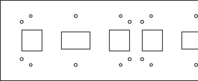
Each display module has threaded holes on the reverse side for fastening to the body. The modules are designed for outdoor installation and are completely sealed from the outside. When installed in a case, it is necessary to seal the modules, for which a silicone gasket is included in the kit. For additional sealing, it is advisable to additionally seal the joints between the modules with acid-free polymerization silicone. At the same time, you cannot fill the groove located around the circumference of the module with silicone; it is intended to drain water. The modules are installed on a flat panel with cutouts for electrical connections and ventilation (cooling). For example, a housing panel for installing three modules looks like this:

Each display module has a power connector and two signal connectors. The signal connectors are the same type, but one connector is input, the second is output. When connecting power, use a red wire (VCC contact - +5 Volts) and a black wire (GND contact - Common). All modules are connected in parallel to one power supply. If two or more power supplies are installed in the board, then the modules are distributed evenly between the power supplies, all modules are connected in parallel along the GND line, and each group is connected to its own power supply separately along the VCC power line.

The signal connectors on the modules are designated IN and OUT (for example, JIN, JOUT, or arrows to the connector are the input, away from the connector is the output). A simple running line, when there are few modules and they are located in one row, has a simple connection - the cable from the controller is connected to the right module at the input, the output of the right module is connected to the input of the next module, and so on. The signal cable is marked with the first line in red. When connecting connectors, it is necessary to observe the orientation of the connectors - they are marked with the first contact. Modules in more complex boards are connected in groups to their controller output. If there are not enough controller outputs, an output expansion board - a hub - is installed. In this case, the diagram for connecting the modules is specified when purchasing the kit.
The power supply and controller are fixed inside the display body in a convenient place. The power supply can heat up significantly, so it is better to mount it on the back wall, and it is advisable to make the back wall from a thermally conductive material (metal, aluminum composite).
Before installing the scoreboard, it must be checked. To do this, you need to install the control program on your computer and follow the steps specified in the program description.
It is almost impossible to assemble a ticker on industrial-style LEDs without microcontroller programming skills and knowledge of data exchange protocols. Below is a simple diagram of a small LED display. If you are not afraid of difficulties and do not want to overpay for the finished product, you can purchase basic modules from which the product will be assembled.
But I would like to talk about a non-standard solution to a problem with minimal financial investment - how to make a ticker from LEDs using Arduino as a controller.
Schematic diagram of a creeping line on LEDs

The controller interacts through a special interface with external input devices. This could be a regular keyboard, a computer, or a smartphone. Based on the data obtained, a complete digital image matrix is formed, which is subsequently displayed on a board with indicators.
Self-assembly of the ticker can be done on an Arduino-based control module and several LED blocks on the controller

The module consists of both a controller and a block of 8x8 LED elements. This element size is the minimum for displaying characters. The fact is that all dot matrix printers generated images for printing based on this format.
Controller max7219
The max7219 controller is a 64-cell communication and memory interface unit for controlling LEDs. In memory, all data is stored in the form of a two-dimensional array.

Information is transferred via the SPI interface. SPI is a three-wire interface for two-way data transfer between devices. You can read more about the operating principle of this interface.
To interact between the controller and the Arduino board, only three channels are used: DIN, CS, CLK.
You can connect up to four such LED modules to the standard connectors of the controller board, creating an 8 x 32 point display. To increase the number of connected segments, you can assemble a simple multiplexer that will switch control signals to the desired module. In this way, it is possible to display information on dozens of matrices. The operation of all LCD displays is based on this principle.
To facilitate the transfer of data flow to Arduino, there is a special library LedControlMS.
This is a video of an example of the library working with an LED display:
More details about matrix control using a microcontroller can be read at the link.
Interface for entering information for subsequent output to the LED matrix
In order to change the displayed text at your discretion, you will need an information input device.
Ways to transfer information to the Arduino controller:
- via a keyboard with a PS2 interface;
- via software keyboard;
- via smartphone.
There are many options for exchanging data with the controller board, in addition to the standard connection to a computer via the ICP protocol.
The Arduino IDE shell has a built-in library for working with the PS2 keyboard. You can use software modules to work with a standard eight-button Arduino keyboard. The input organization is built on the principle of mobile phones, when several characters are “suspended” on one button. By connecting a bluetooth module to the Arduino board, it is possible to transmit test information via a smartphone.
When you understand the organization of the ticker on standard Arduino modules, you can move on to the next stage.
An LED board can decorate a design and make advertising dynamic and concise. A store or office sign will attract the attention of potential visitors and provide information about discounts, promotions, etc.
This video tutorial shows how to make such an advertisement. You will get a real creeping line, which is used on outdoor commercial advertising. It will be based on 2 matrix modules. Also Arduino nano, crown holder, battery and switch. You can buy all spare parts in this Chinese store.
What should be done


Let's connect two LED modules with hot glue. We will attach the remaining elements to the back. We will attach the Arduino so that you can program it without taking it off. We'll attach a button on top.
We solder two modules through jumpers. We will also solder the Arduino to the input and button. Let's make a lid from a corner with our own hands.
Electronic part
How to upload a sketch to Arduino:
www.arduino.cc/en/Main/Software.
driver https://goo.gl/24cFBZ.
sketch https://goo.gl/hxfJnu
library https://goo.gl/4GnOLq
library https://goo.gl/8XaOzI
You need to download and install two libraries. And you can change the number of matrices that are used. In this case, there are 8 matrices, each of them has 8x8 LEDs (64 pieces). They will be placed to line up line by line.
The resulting product does not yet display a line in Russian, but on the Internet you will find tips on how to set up the Cyrillic alphabet.
Ivailo Vasilev
Characteristics of LED Matrix Display
- Matrix format 40×7 points;
- Display time, date, indoor and outdoor temperature, text messages;
- Automatic transition from winter to summer time and vice versa;
- The real-time clock operates without external power for more than one week;
- Indoor temperature measurement (0…+75) °C, accuracy ±0.5 °C;
- Outdoor temperature measurement (-40…+75) °C, accuracy ±0.5 °C;
- Supports static and dynamic messages with various effects;
- Full set of Cyrillic characters and special characters;
- Memory for 10 messages, up to 250 characters each;
- Automatic brightness adjustment;
- IR remote control for customizing messages;
- Supply voltage: 12…24 V DC;
- Front panel size 305 × 69 mm.
Schematic diagram
The device consists of two parts: a control unit and a display unit. The two circuit boards are connected to each other using a pair of double-row connectors and separated by four bushings. One of the connectors is used to transmit electrical signals, the other is used only as a mechanical connecting element.
The main component of the device is the PIC18F252 (U9) microcontroller. It controls all functions and implements the LED matrix control algorithm.
The LEDs are connected in a 40×7 matrix. The cathodes connected together form the columns of the matrix, and the anodes form the rows. The matrix is controlled dynamically - row by row. The LEDs of the matrices are switched by specialized driver chips STP16CP05 (U101...U103) manufactured by .

|
Inscriptions on the photo |
|
|
Supply voltage |
|
|
IR receiver |
|
|
Light sensor |
|
|
Temperature sensors |
|
|
INSTALLATION |
|
|
Internal |
|
Each of these chips contains a 16-bit serial-in/parallel-out shift register and a 16-out latch register. The open-drain outputs of this register allow you to connect a load with a supply voltage of up to 20 V. The constant current of the outputs varies from 5 to 100 mA and is regulated by an external resistor (R115…R117). Three LED drivers are connected in cascade (one after the other) and controlled by a microcontroller via the SPI interface. The microcontroller sends a 48-bit word, loading one line. The 40 least significant digits represent the state of the row LEDs (1-on, 0-off). The 7 most significant digits are used to control the anodes through 7 transistor switches (VT101...VT107). The 40th bit remains unused. The microcontroller sends a 48-bit word every millisecond.
For 7 cycles, lines one through seven are displayed, then there is an 8th additional cycle used to measure temperature. Thus, the display refresh rate is 125 Hz. To adjust the brightness of the display, the control inputs of the “output resolution” (OE) microcircuits are used. Each line cycle begins with the setting "log. 0" on pin OE (outputs enabled). The duration of this signal, which is generated by the microcontroller PWM module, varies depending on the desired brightness.
It should be noted that the numbers of columns and rows of the matrix do not correspond to the corresponding pins of the microcircuits (U101...U103). This is done to simplify the layout of printed circuit boards. The bits corresponding to specific LEDs are generated at the software level.
Download the diagram in PDF format
Real time clock and calendar
The real time clock is implemented on the U10 chip - PCF8583. It directly contains a clock with all the necessary counters and registers, a calendar, an alarm clock, a 32768 Hz oscillator and I 2 C interface circuits. Its power consumption is very low (about 10 μA), and the supply voltage can be in the range of 1...6 V. Such characteristics guarantee long-term operation when using a small lithium battery, or even a storage capacitor. The developed printed circuit board provides both options.
The standard size of the lithium battery is 2032. When experimentally installing a capacitor with a capacity of 1 F, after turning off the power, the clock ran for more than a week. To reduce the forward voltage drop, VD10, VD11 and VD12 should be Schottky diodes. Trimmer capacitor C21 is used to set the generator frequency to 32768 Hz. For communication via the I 2 C bus, a synchronous serial port (MSSP) module of the PIC18F252 microcontroller is used. The module operates in “master” mode. An external EEPROM (U11) can be connected to the same bus to increase the amount of data stored. In the presented version of the microcontroller firmware, additional memory is not required, so there is no need to install the U11 chip.

Temperature measurement
To measure air temperature, LM35 sensors (U5, U6) are used. They are calibrated directly in degrees Celsius. The output signal has a coefficient of 10 mV/°C. The supply voltage must be between 4 and 30 V. For measurements over the full temperature range, a negative voltage must be applied to the sensor outputs through resistors R4 and R5. To do this, the lower terminals of the sensors are connected to the analog ground through two diodes (VD4, VD5 and VD6, VD7), which raise its potential to approximately 1.4 V. When the sensors are connected in this way, the +5 V source voltage will not be enough to power them, so it is added to the circuit stabilizer U1 (78L09).
The signal from the sensor is removed between its output and the negative contact. The voltage between these two terminals is proportional to the temperature, and its sign (+ or -) indicates the nature of the temperature (above or below 0 ° C). The sensors are connected to the device using three-wire cables. The software is designed to measure internal temperature using U6 and external temperature using U5.
Analog-to-digital converter
The outputs of both LM35 sensors are connected to the U4 - MCP3302 chip. This is a successive approximation ADC. It provides measurements with a resolution of 13 bits (12 bits plus sign bit). The MCP3302 has 4 analog inputs that can be configured as either 4 separate or 2 differential. In this circuit, a variant with two differential inputs is used to convert bipolar voltage from LM35 temperature sensors. The reference voltage for the sensors is generated by the U7-LM336 chip.
Using trimmer resistor RP1, the reference voltage is set to 2.55 V. Diodes VD8 and VD9 are needed for temperature compensation. The MCP3302 has an SPI interface using four signal lines. Using these lines, the microcontroller (U9) controls the ADC. To increase measurement accuracy, the analog ground is decoupled from the digital ground using a small inductance (L6). This is a ferrite choke for surface mounting Z600 size 0805. The same chokes are used to decouple the power supply of the ADC, temperature sensors and the reference voltage source (L4 and L5).

Brightness control
To automatically adjust the display brightness, an integrated light sensor U8 (TSL257) is used. Its output voltage is directly proportional to the intensity of light incident on the built-in photodiode. This voltage is measured by the microcontroller's own ADC. The duty cycle of the PWM module of the microcontroller depends on the measured value, hence the change in the brightness of the LED panel. To avoid unwanted brightness fluctuations, a small delay in controlling the PWM module is introduced in software.
Display functions
Display settings are made by the user using three buttons S1…S3. The names of these buttons are:
- S1 - Up;
- S2 - Down;
- S3 - Installation.
Setting the clock
To enter the setup mode, press the “Setup” button once. The display will show "Settings" . To set the time and date, press the Up or Down button until the text appears "Set time" . Press the “Set” button again and the display will show the current time with the clock digits flashing. Use the Up or Down buttons to set the current hour. Then press the "Set" button to enter the minutes. When the current time in minutes is set, the display switches to date setting. Set the day, month and year in sequence and click the “Set” button to complete the setup process. The program will automatically calculate the day of the week.
If the date is selected incorrectly (for example, 02/29/10), the message “ ERROR ", and then the program will return to the beginning of the date setting. If the date is set correctly, the display will show the set time with a flashing "OK" , and the program will wait for confirmation of the new time and date values. If you press the “Up” button, the new values will be ignored and the program will return to the “ Settings" If the Down button is pressed, the device will return to the first step of the procedure " Set time" When you press the “Set” button, the new time and date values are accepted, the seconds are reset and the display returns to normal mode. The program automatically changes the clock to summer time (+1 hour). This happens on the last Sunday in March at 3:00 am. Return to winter time (-1 hour) takes place on the last Sunday in October at 4:00 am.
The ending follows
Preface: EQSRF Plant thanks you for visiting this page.
Hi all!
On the Internet, we have noticed an increase in demand for self-assembly; in a word, we want to assemble tickers and earn money or save money. In this article, we will look at how you can make a ticker board with your own hands.
For this process we will need components for tickers:
IN BY It is possible to set more than 30 types of different effects: delay and speed of text playback, animation, time and temperature, and much more. This is quite a fascinating process that will give you a lot of pleasant emotions and positive impressions.)
In order for the temperature to be displayed on the creeping line display, you will need to purchase one that is soldered to controller(motherboard) ticker.
If this method seems rather incomprehensible and difficult to you, our Factory is ready to produce for you a ready-made ticker in various colors at an excellent price. In general, our plant is engaged not only in the sale of components for tickers, but also in the production of a full cycle of tickers, LED screens, pharmacy crosses of all sizes, colors and automobile tickers. That's all we wanted to write to you about in this article.
We are sure this information was useful to you.
You have a wonderful opportunity to take a training course for dealers and wholesale customers. Link
Thank you everyone and may the money be with you!
You can send a request for a free estimate by emailing the size and color of your LED string
- In contact with 0
- Google+ 0
- OK 0
- Facebook 0